My Lathe

After thinking about it for quite a while I finally took the plunge and bought a lathe, I've always liked making things, usually it's with a soldering iron and some electronic components but now I'd like to try my hand at turning metal.
Anyway here are some of my experiences and discoveries, I hope someone finds them useful.
Showing posts with label mini lathe. Show all posts

Saturday, 31 January 2015

Mini Lathe DIY Autofeed stop - Part 2

The bracket finally arrived for the auto-feed stop. A friend at work had it done for me, he uses a firm that uses high pressure water jets to cut aluminium, I gave him a 2D CAD file of the shape and they cut it out of a 20mm thick piece of Aluminium using water!

As is normal, for me at least, there were a couple of things that didn't quite fit, the top of the middle upright clashed with the gear for the cross slide travel so I removed 10mm from the top and then the front edge clashed with the back of the half nuts so I made it 5mm thinner.

Original design with material removed
Bracket Clearance
It was apparent that I wouldn't be able to put a securing bolt through the front of the bracket as there was just no clearance from the leadscrew so I drilled and tapped from the rear, you need to put the spanner through the gap in the bed but it works fine and will be less fiddly to tighten once I shorten the bolt.
Access through the bed to tighten the bolt
So, once I got it fitted to the lathe and tightened up it was time to see if it actually worked.

Side view
Front view
I engaged the auto-feed and it slowly moved along and when the lever hit the bracket it disengaged the auto-feed.

Success, it needs a bit more work and tidying up, I want to shape the lever and line it up a bit better and add a long M6 bolt in the hole in the bracket to give me some fine adjustment.

I'm also thinking about adding a spring and a latch mechanism which will fully disengage the lever when it's tripped as it currently stops the auto feed but doesn't fully reset the lever position.

I hope to test it out later with a thread I want to cut, if everything works out I will have succeeded in adding auto feed stop to the lathe with minimal modifications to the lathe itself.

If anyone wants the 3D model I can make it public on tinkercad.com, just ask in the comments.

Thursday, 15 January 2015

Mini Lathe DIY Autofeed stop

Another project for my lathe is a way to stop the auto feed automatically instead of me having to raise the lever myself.
There are a few mod's out there already which address this issue with the mini lathe but they require quite a bit of machining or fabrication of brackets.
I spent some time standing and staring at the lathe trying to come up with some ideas that need the least amount of interference with the lathe and not a lot of machining.

I came up with the idea of adding a second arm to the half nut lever that points downwards when the autofeed is engaged, this would then hit a striker that could be adjusted along the axis of the lathe bed.

The bolt was for testing purposes, I intend to install a shaped lever with a flat surface etc.

The next challenge was to make something that would fit to the lathe and be adjustable and not interfere with the normal use of the lathe.

I thought about a block of wood secured to the control box housing with a length of threaded bar sticking out to hit the lever as it traveled towards the chuck but his meant that I would need 2 or 3 different lengths to cover the range of travel needed.

I considered having something clamped to the lathe bed that would stick out and down to hit the lever but this my get in the way and need to be removed in normal usage.

I settled on a design that would clamp to the underneath of the lathe on one of the longitudinal ribs (can't think what they are actually called !)

Here's some CAD I did whilst working it out. (Done in Tinkercad.com)
Just waiting for the bracket to be made and then we'll see if it works........

Monday, 12 January 2015

Thread Cutting Problem

After owning the lathe for a couple of months an getting used to it I decided it was time to attempt cutting threads, I'd watched loads and loads of YouTube videos on the subject and felt I'd got the basic idea so it was time to give it a go.

I'd bought a quick change toolpost which would allow me to swap the cutting tools without having to shim my tools for their different heights, I went for a Myford type from Warco but it needed a 11.2mm stud whereas mine was only 10mm so it was just the project I needed to try out turning a new toolpost stud to fit.

After changing the gears to get a 1.5mm pitch I found that whenever I engaged the leadscrew it would force the reverse tumbler gears out of mesh without even trying to make a cut...... not good!

After a phone call to Warco and a discussion with the technician I decided to see how difficult to turn the lead screw was and yes it was very difficult to turn, not really possible with my fingers even with the gear removed from the end.
I removed the two cap screws from the right hand bearing and it sprung away from the lathe bed around 10mm, hmmm! I thought I'd found the problem, the leadscrew was not parallel to the lathe bed, something at the other end was out of true.

After removing the leadscrew and inspecting the left hand bearing I noticed that there seemed to be a clash between the bearing and the bracket that hold/adjusts the 'B' and 'C' gears.

Yellow line showing the foul
I removed the bracket completely and enlarged the hole where the clash occurred with the bearing.
Still with the bracket removed, I re-fitted the leadscrew and checked how free it was with both bearings re-fitted, it was still a little stiffer than I thought it should be but easier than with the bracket fitted, whenever I tightened up the right hand bearing it was stiffer to turn so I added a thin shim under the left hand bearing and then it ran freely using my fingers when both bearings were fully tightened down.


After re-assembling the bracket and gears I then aligned the apron by loosening the cap screws and engaging the half nuts then re-tightening, when you engage the half nuts the leadscrew should not move significantly side to side, if it moves upwards the you may want to place a shim between the apron and the cross slide.


The other thing I did was to improve the locating of the leadscrew direction lever, as it had slipped out of the detent so many times it had worn a groove in the casting so I drilled a 3mm hole slightly above the original detent. ****Be careful when drilling into the casting, the drive belt runs under that part of the casting ****

I then turned down part of the plunger to give it a 3mm (just under) parallel section that would go into the new hole and secure the direction lever in place.
The plunger still has the tapered point so it will still work with the other two detents.

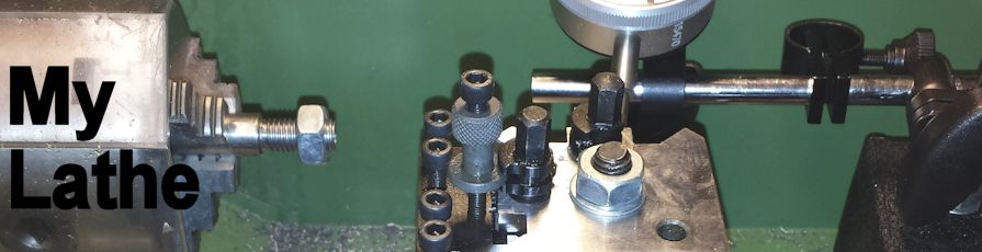
Following these refinements I successfully made an new stud for my quick change toolpost, I also thought the lathe was a bit quieter as well.
New stud for my new toolpost
.

Saturday, 10 January 2015

Second thing - DIY Digital DRO

One of the important things about using the lathe is keeping track of how much material you're taking off, once removed it's very difficult to put it back on....

Don't forget to divide the amount you want to remove from the diameter by 2 as you are removing material from both sides .... sort of.
Using the dial on the slide is OK but I've seen lathes with digital readouts, how much are those I wonder?
After some research I found  a really good alternative to the standard slides and readouts available from the usual suppliers, I found a DIY version for around a fiver (£5) plus a bit of DIY.

It's based on this digital LCD tyre depth gauge off ebay.  It's basically a variant of the digital vernier but without the sharp pointy bits.

I attached mine on the cross slide by mounting a piece of steel plate using the travelling steady mounting holes (at least I think they are for the travelling steady) this then allowed me to use a magnet to stick the body of the gauge to, the end of the plunger has a magnet glues to it so that it will stick to the cross slide.  It could also be stuck on the lathe bed and measure the saddle travel.

My DIY DRO attached to the lathe
The plunger magnets are basically 2 very small neodymium magnets glued inside a small mild steel tube (turned on the lathe 7mmx4mm with a 2mm hole but these dimensions can be what you need) glued on the end of the plunger.


One of the problems with the mini lathe is actually finding space to mount the gauge as there's not a lot of room.

What I like to do is touch the tool to the material to be cut and set the DRO to '000' then move to tool to the right and move in the tool until I've reached half the amount I need to remove then reset the DRO to '0.00' and then turn down the material until I reach the '0.00' point and that's that.
So far I've found it quite accurate but noticed that it gets covered in swarf when in use, I thought about forming a piece of thin perspex to curve round the gauge and protect it from chips but then found an empty rectangular packet in the recycling bin that was about the size of the gauge but made of clear plastic, thin but strong enough to keep it's shape, this slid over the gauge and protected it completely and was flexible enough to still be able to press the buttons.

DIY DRO with plastic cover
It's also possible to connect to these gauges and get a serial data stream that could be read by an Arduino and shown on a larger LCD and there is a project out there that uses a Bluetooth interface to display the data on your smart phone here, one for my other blog maybe.

Comments/ideas/feedback welcomed.

Tuesday, 6 January 2015

First Thing

As I imagine most people do after buying a lathe nowadays, I also spent a lot of time watching YouTube videos.

One of my favourites is mrpete222 AKA Tubalcain, he's a retired teacher in the states who's done hundreds, if not 1000s, of videos on Milling, Turning and even casting aluminium parts, a definite must watch.

One of the little jobs he did made me think about doing the same thing for my little lathe, a knurled thumb screw to lock/release the measuring dial on the cross slide.
This replaces the supplied grub-screw and lets you set '0' on the dials as a deference point and then lock it in.
Grub-screw replaced by thumb-screw
Instead of turning the M6 thread from scratch though I cheated by using an M6 Bolt, all I did was shorten it and turn down the head so it was round and then I would have knurled the head ...if I had a knurling tool .. as I don't I just took my Dremel clone and put some cuts around the circumference of the head.

I also turned a small brass disc to put under the screw to protect the shaft from wear.
Assembly of parts

All in all it works pretty well but my next project meant that I don't often use the dials on the cross slide ... that's in the next post.

Friday, 2 January 2015

Which one, Where from?

So, once the decision was made to buy a lathe the next step was to research what was available within my budget and where would be best to get it from.

The second decision to be made was to buy new or second hand.

There are a few well known makes of lathes out there like Myford, Drummond etc. Myford lathes
Myford ML7 Lathe
seem to be one of the more common makes on the second hand market.
After looking through quite a lot of adverts for second hand lathes I decided that I didn't really have the experience needed to be able to look at a lathe and decide if it was OK or not and, even second hand, the cost was often more than the cost of a budget mini lathe.
Another thing to consider was the distance you may need to travel to pick up the lathe and don't forget, they are quite heavy.


Anyway, I decided to buy a new one and this would need to be an online purchase as there aren't any suppliers anywhere close to me.

Based on my web research it looks like the main contenders in the budget lathe market come from China made by a company called SIEG.  There are 3 main spec's of lathe, C1, C2 and C3, the C3 being the best spec.

These lathes are sold in the UK by distributors and there also some customised versions badged as their own brand.

The cost varies between £350 - £600 for one of the mini lathes, here are some of the places I looked.
www.arceurotrade.co.uk
www.warco.co.uk
www.axminster.co.uk
www.ebay.co.uk

The one I went for

I eventually bought mine from Warco.co.uk, (link) mainly because it came with a slightly better spec. than some of the others and also the price included courier delivery.

Having had the lathe for a few months I did come across a few quality issues that needed addressing and this is where I found out what a good company Warco was to deal with.
Whenever I had an issue with anything Warco always had someone ring me back to discuss the issue and then sent out new parts straight away, this was quite a pleasant surprise because my experience in dealing with most companies, when things go wrong, is usually a nightmare.

I will be going over some of the issues and solutions in later posts.


The First Entry

Having had a blog for my interest in electronics and the Arduino open source project for some time I decided to start a new blog to share my experiences with my new lathe, purchased in 2014, rather that confuse my existing blog.


Let's get one thing out in the open at the very beginning, I'm not an expert tool maker or an experienced hobby engineer I'm an electronics engineer with an interest in making things and a lathe is now part of my toolbox.

There is already quite a lot of information out there for lathes but most of it seems to be for larger/ older  lathes, way over my budget and probably too big to fit in my garage.

What I'd like to do is create some entries describing the process of how I went about buying a budget lathe and then moving on to the things I learned from reading other peoples blogs and many visits to YouTube which helped me improve both my lathe and my understanding of the lathe.

As you may be aware from reading my other blog, I'm not a prolific blogger and there may be quite some time between blogs.......